Sedimentation is the Unit operation in which the suspended solids in the water are settled with help of gravitational forces. The settled solids are scraped, collected & pushed out of the unit. The unit is called Gravity Clarifier. Basically there are two types of Sedimentations carried out in Biological treatment of Sewage/Waste water. Primary sedimentation is separation of solids before Biological treatment & secondary sedimentation/clarification is the one carried out after biological treatment.
The efficiency of the sedimentation results in a significant reduction in the discharge of BOD, COD, heavy metals etc. The bigger suspended solids (Flocs) in the effluent better are settling characteristics. Stokes’ law highlights the importance of the floc size for the speed of sedimentation.
Stokes’ law:
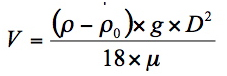 V = sedimentation rate in m / s
ρ = density of solids kg / m³
ρ 0 = density of water kg / m³
g = 9.81 m / s 2
μ = viscosity of water in Pa (at 20 ° C the viscosity of water is 1.06 x 10 -3 Pa)
D = diameter of the particle in m.
When feeding the clarifier it is possible to facilitate the formation of large flocs by installing baffles inlet that use the kinetic energy of water for agglomerating the flocs thereby increasing size.
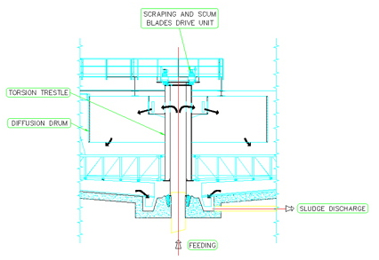 In the secondary clarifiers is also very important to the type of scraper blade profile and the size of the central well of the collection. Indeed, given the enormous volume of “sludge” with respect to the input flow rate (50%), it can be assumed that the characteristics the mud differ little from those of the clarified water (in static conditions the clarified water and sludge are layered with the surface of horizontal separation), and that then the flocs, due to the slight slope of the bottom (~ 4%), to flow without the need aid to the central well. But it should not be forgotten that the particles that touch the bottom, and by those that are placed on, join and lose the properties of “fluid” must therefore be collected and pushed actively towards the centre well before the layer becomes too thick and gets adhered and especially before the anoxic conditions start occurring leading to denitrification leading to formation of floating flocs. So it may be said that scraper blades should quickly push all the settled solids from the periphery to the centre well. This is achieved by giving the blades a continuous & logarithmic profile.
Types of Settling
The types of settling that occur in wastewater treatment are summarized in Table below.
Type III settling is the predominant mechanism in secondary clarifiers and governs
design, although Types I, II, and IV settling may also occur to a limited extent.
| Type Of Settling | Description | Solids Concentration | Primary Mechanism |
| Non-flocculant Settling | No flocculation. Particles settle independently of each other. | Very Low | Grit Removal |
| Flocculant Settling | Particles flocculate & settle as single particle. | Low | Primary Clarification |
| Zone Settling | Flocculated Particles settle as layer or zone. | High | Secondary Clarification |
| Compression Settling | Increased contact between flocculated particles which are mechanically supported by particles below. As the layers compress, water is squeezed out. | Very High | Sludge Thickening |
Functions of a Clarifier
The final clarifier must perform two primary functions: clarification and thickening.
Clarification is the separation of solids from the liquid stream to produce a clarified effluent with low effluent suspended solids (ESS) levels. Thickening is the conveyance of sludge particles to the bottom of the tank, resulting
in a slightly con cen tra ted underflow, or return activated sludge (RAS).
Clarification involves less than 2 percent of the solids that enter the clarifier. A
rise in ESS is an indication of clarification failure. Thickening involves a relatively larger fraction of the solids (> 98 percent). Thickening failure results in a rise in sludge blanket depth. If the clarifier fails in either of these functions, the following would been countered:
1. Effluent TSS permit violations.
2. Unintentional wasting of solids with the effluent leading to a reduction of solids
retention time (SRT), which could potentially impact the biological process.
Clarifiers may also be used for temporary sludge storage during diurnal flow
fluctuations. Long – term sludge storage in clarifiers should be always avoided, since it results in a substantial portion of the biomass being held in the clarifier in a relatively in active state, rather than in the aeration tank, where oxygen and
substrate are available for the desired biological reactions to occur. Also, deep sludge blankets could potentially cause denitrification and secondary phosphorus release as discussed above in design of scraper blades.
Some design aspects:
Overflow Rate: As the floc settles in a clarifier, the displaced
water rises upward. The upward velocity of water is termed the overflow rate (OFR), and is determined by dividing flow by the clarifier by the surface area.
When a clarifier is opera ted at a specified OFR, all particles having settling velocities higher than the operating OFR will be removed , while particles with lower settling velocities will be carried over the effluent weir. By selecting a proper OFR, good clarification is ensured. When the clarifier is not thickening limited (rising sludge blanket), its capacity may be increased by improving settleability.
The clarifier solids load rate (SLR) in lb/d/ft2, represents the mass of solids applied per unit area per unit time. It is calculated as follows:
SLR = 8.34*(Q + Qras)*X/A
Where,
Q = Influent flow, mgd
Qras = RAS flow, mgd
X = MLSS concentration, mg/L
A = Clarifier surface area, ft2
The maximum amount of solids that can be conveyed to the bottom of a clarifier is called the limiting flux. When SLR exceeds the limiting flux, a rising sludge blanket (thickening failure) is encountered. Most design engineers prefer to keep the maximum solids loading rate in the range of 25 to 30 lb/d/ft2.
The clarifier solids concentration profile consists of four zones: a clear water zone (h1), a separation zone (h2), a sludge storage zone (h3), and a thickening/sludge removal zone (h4). When the SLR exceeds the limiting flux, the sludge storage zone (h3) expands to accumulate the sludge and limits its conveyance to the bottom of the tank. The continued expansion of h3 will result in the sludge interface reaching the effluent weir, causing a loss of solids (clarification failure).
Hydrodynamic Considerations:
The solids capture efficiency is strongly impacted by hydrodynamic characteristics of the clarifier. Features that contribute to improved clarification include:
Even flow splitting to allow the full capacity of all clarifiers to be realized. Poor performance of an overloaded clarifier generally can not be compensated by good performance of an underloaded clarifier.
Energy dissipating inlets to achieve uniform distribution of flow and enhanced flocculation.
Strategically placed internal baffles to minimize short circuiting and density currents.
Deep flocculating centre well to enhance flocculation.
Deep tanks (>15 feet) to allow the sludge blanket to expand and contract in
response to varying operating conditions without causing elevated ESS.
Rapid sludge removal mechanism
It goes without saying that all the above aspects are taken care while designing the Gravity Clarifier System.
The Lamella Clarifier & Tube Settler are not truly Gravity Clarifiers since water is forced through the Lamella/Tubes & hence not been discussed here.