Desalinated water is poor in terms of minerals, making it corrosive and unpalatable. A certain degree of remineralization is necessary in order to overcome these problems. A commonly used remineralization process is to pass desalinated water dosed with CO2 through a bed of limestone or lime slurry dosing, reintroducing bicarbonate alkalinity and calcium hardness to the water.
Carbon dioxide, CO2, is gaining acceptance for pH control in water treatment plant. It reduces high pH levels quickly. It is not stored as an acid solution so it is safer than sulfuric acid. It is non-corrosive to pipes and equipment. It requires less equipment and monitoring costs. It requires no handling costs. It can be utilized via a completely automated system.
CO2 is also used for Re-carbonation for two purposes in a lime-softening plant: (1) for pH adjustment, and (2) for the neutralization and precipitation of the calcium hydroxide in the primary basin effluent in cases where high-magnesium waters are softened by application of excess lime followed by re-carbonation.
Carbon dioxide dissolves in water forming carbonic acid according to the following reaction:
CO2 + H2O = H2CO3
Carbonic acid is then ionized into HCO3- species
H2CO3 = H+ + HCO3-
The pH value is reduced to about 6.0 by dissolving carbon dioxide. Evolution of carbon dioxide from water leads an increase in the pH value according to the reverse of the net reaction of the preceding two reactions:
CO2 + H2O = H+ + HCO3-
Under normal conditions, CaCO3 is only slightly soluble in water. However, its dissolution in water can be enhanced in acidic conditions. The use of CO2 for this purpose is advantageous because it will both lower the pH and convert to alkalinity as the calcite raises the pH of the water. When CO2 is added to water, the acid equivalent of CO2 in water, carbonic acid (H2CO3) is formed, which is regularly used in soft drinks.
In calcite dissolution by CO2, the first step is the carbonic acidification of the water, shown in
CO2 + H2O = H2CO3
Calcite will then react with the carbonic acid as indicated below.
CaCO3 + H2CO3 = Ca2+ + 2HCO3
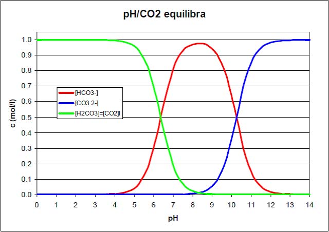
PH & CO2 Equilibrium Diagram
Liquid CO2 is stored in insulated storage tanks with refrigeration system. Ambient heating of the storage tank results in the heat entry to the storage tank even though it is well insulated. This heat entry results into vaporization of the stored liquid CO2 and if left unchecked will result into higher tank pressure. If no CO2 vapour/gas is being withdrawn from the storage tank, the refrigeration system is used to cool the vapor in the tank vapour space. This cooling of the vapour/gas results in a phase change of the vapour to liquid in the vapour space and thus reduce the storage tank pressure to an acceptable level. Otherwise, the storage tank pressure will continue to increase and eventually reach the set point of the storage tank safety relief valves and CO2 vapour/gas will then be vented to atmosphere until the pressure level in the tank is reduced to the reset pressure of the safety relief valve. However, if vapour is being withdrawn from the tank process, then the vapour being evaporated by the ambient heating tends to help control the tank pressure without running the tank refrigeration system. If the CO2, vapour/gas demand exceeds the CO2 vapor/gas evolution generated by ambient heating, then the vaporizer will be energized to augment the CO2 vapor/gas supply as required by the system.
The storage tank refrigerant system will maintain the liquid in the tank at approximately 0 ºF by maintaining the vapor space during periods of low or no CO2 vapor withdrawal. The vaporizer is a pressure building vaporizer. This unit receives liquid CO2 from the bottom of the storage tank. The vaporizer heating element heats the liquid CO2. As more heat is added to the liquid CO2 in the vaporizer pot, the liquid either in the pot or in the vaporizer return line to the storage tank goes through a phase change and CO2 vapor/gas is produced. The vapor returns to the vapor space in the storage tank. The liquid CO2 vaporizer control panel controls the operation of the above the equilibrium pressure at the minimum allowable pressure vessel temperature and the pressure where liquid CO2 undergoes the liquid to solid phase change. As CO2 in the vaporizer is heated, the tank pressure rises, and at a pre-defined set pressure the vaporizer is automatically de-energized. The liquid/vapor discharge side of the CO2,vaporizer is piped to the tank vapor space. Therefore the normal operating pressure range for the storage tank is maintained.
The process CO2, vapor/gas is piped from the storage tank vapor space to the vapor heater and then to CO2, gas feed (pH control) panel. The pH of the process water in the basin is controlled by diffusing CO2 gas in the basin through a fine bubble diffuser assembly and measuring the pH of the water in the basin following the introduction of the CO2 gas. The gas feed panel CO2 flow control valve controls the flow of CO2 gas being introduced.
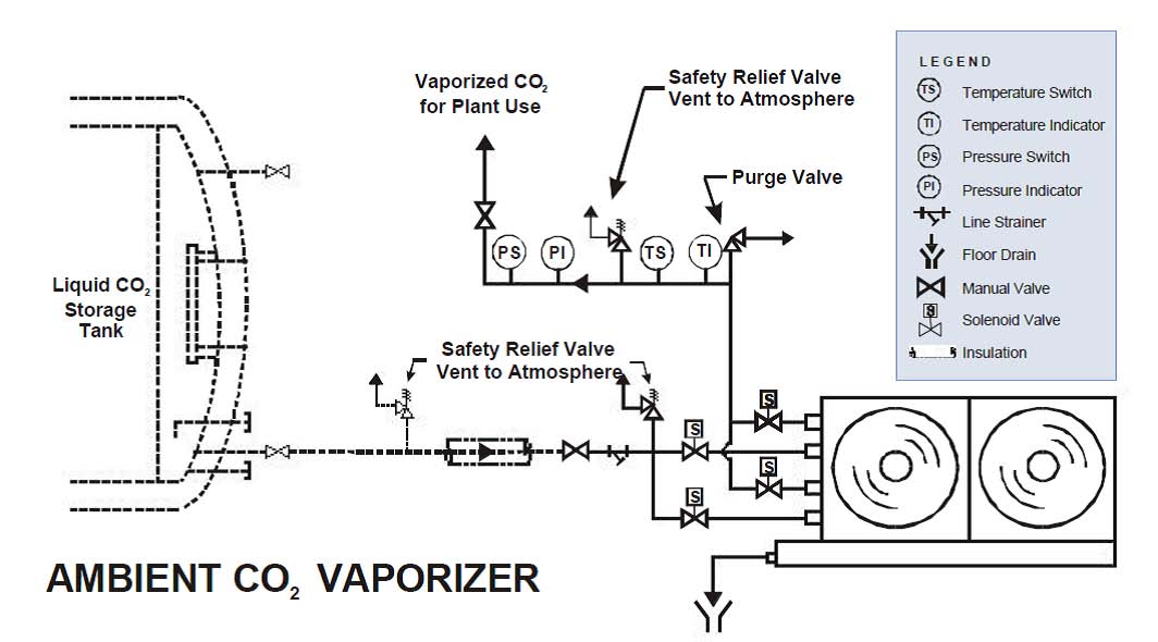
Typical CO2 Vaporizer Schematic
Typically a CO2 dosing systems contains following components:
- CO2 Storage Tank(s): The storage tanks are fully insulated mild steel pressure vessels. The CO2 is stored at around 300 psi & (-) 20C. A complete automatic refrigeration system is provided to maintain storage tank at (-) 20 C and 300 psi. The tank is complete with filling/withdrawal lines & necessary instrumentation for safe operation.
- Vaporizer/Vapour Heater: A Vaporizer is provided to vaporize the liquid CO2 to gaseous state as per requirement. Vapour heater is provided to heat (-) 20C CO2 to near room temperature. Both Vaporizer & vapour heater are provided with necessary safety and measurement instrumentation.
- CO2 Regulator: Carbon dioxide pressure reducing regulator is provided each storage tank, which is mounted in the CO2 pipeline after dioxide vapor heater. Each regulator shall be used to reduce the pressure from approximately 300 psig to 100 psig. The outlet pressure of each regulator shall be easily adjusted through the use of an adjustment screw.
- CO2 Diffusers: A set CO2 gas diffuser assembly with tube type fused alumina, porous, fine bubble diffusers are provided to input carbon dioxide into the re-carbonation basin.
The CO2 system is provided with safety features like CO2 gas leakage detector etc.