WHAT IS MIXED BED UNITS:
Mixed Bed Units are an ion exchange method used where superior water quality is needed. They are typically the last treatment step in the water treatment process train. They are normally positioned downstream of either individual two-bed working ion exchange units or reverse osmosis systems, further treating the effluent of these demineralizers. For low TDS (Total Dissolved Solids) waters, they can be used as stand alone ion exchange units. In this application they are often referred to as “Working Mixed Beds”. In condensate polishing applications, you can use Mixed Bed Ion Exchange to remove condensate contamination before reuseMixed Beds are ion exchangers that have both Cation and Anion resins, mixed in a single vessel. The resin bed is in the both H-OH form. These units are normally designed so that they can be automatically operated, with all the necessary internals, instruments, components and controls. Each unit is mounted on a rigid, structural steel skid base.The last traces of TDS and silica can be removed on a resin bed where highly regenerated strong acid cation and strong base anion resins are mixed.Mixed bed units deliver an excellent treated water quality, but are complicated to regenerate, as the resins must first be separated by back washing before regeneration. Additionally, they require large amounts of chemicals, and the hydraulic conditions for regeneration are not optimal. Therefore, mixed beds are usually only used to treat pre-demineralised water, when the service run is long.Mixed bed polishing produces water with less than 1.0 µS/cm conductivity a conductivity of less than 1.0 µS/cm. With a sophisticated design and appropriate resins, the conductivity of pure water (
WORKING:
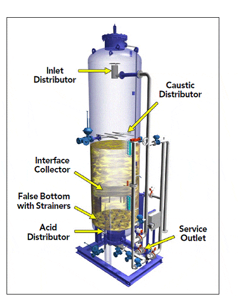
During the service cycle, water enters the unit through the inlet distributor at the top of the vessel, and is evenly distributed across the resin bed. As the water flows through the resin bed, its ionic contaminants are exchanged for H and OH ions on the resin beads. This removes the ionic contaminants from the water, producing highly purified Demineralized water. The treated water then passes through the false bottom under drain strainers to the outlet piping at the bottom of the Unit. When the unit’s capacity is exhausted, regeneration begins. The resin is backwashed and hydraulically classified based on their densities, and after the bed settles, regeneration is carried out. Caustic Sodium hydroxide is introduced through the downflow.
regenerant distributor, and acid is introduced through the upflow regenerant header. The interface collector receives spent acid and caustic for disposal. A slow rinse displaces regenerant acid and caustic, then the full bed is rinsed with service water. The vessel is drained until the water level is just above the bed surface. The resins are then re-mixed with air. The vessel is refilled and the bed is rinsed before the unit is returned to service.
A Summary of Regeneration Steps is given below:
- Backwash – Classify
- Settle Bed
- Acid & Caustic Injection
- Acid & Caustic Displacement
- Drain Down
- Air Mix
- Refill
- Rinse
Typical Applications:
- Treatment of water pre-demineralised with ion exchange resins
- Polishing of reverse osmosis permeate
- Polishing of sea water distillate
- Treatment of turbine condensate in power stations
- Treatment of process condensate in various industries
- Production of ultra-pure water for the semi-conductors-industry

