 Gravity filters are so named because water flows through the filter bed by gravity instead of being pushed through by a pump or a high static head of pressure.
These filters are commonly found in municipal drinking water applications, but in industrial settings are usually only associated with an upstream clarifier.
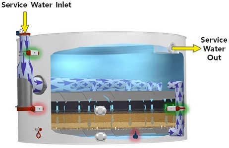
Process and Operations Review : Water flows into the middle compartment and is distributed over a bed of filter media by an inlet distributor. Gravity pulls the service water through the filter media bed and into the lower compartment. The upper compartment stores water for the backwash cycle.
The filter media bed consists of stratified anthracite and sand, with the largest media particles on top and the smallest on the bottom. After the water flows through the media bed, it passes through strainers that hold back the filter media particles, but allow the water to be collected in a plenum. From the plenum, the water flows through the transfer pipe into the backwash storage chamber (above the bed). As the water reaches the top of the backwash storage container, it overflows through the service outlet.
Periodically, the media bed must be backwashed to remove the particles it collects. Backwash is initiated when the pressure drop through the media bed exceeds a set point; it can also be initiated on a timed basis. The water supply for the backwash cycle is stored in the backwash storage chamber above the filter bed. The backwash flow rate is much higher than the normal service flow rate. The media bed compartment has sufficient freeboard to allow expansion of the media bed during the backwash cycle.
Another method of cleaning the media bed is with an optional air scour system. The bed is drained down and air is blown up through the media bed, causing the filter particles to scrub impurities off of each other. If the air scour option is selected, a valve is added to the transfer pipe to hold back the water in the backwash chamber during the drain down and air scour steps.
Gravity filters are occasionally provided with external backwash capability. This feature provides a constant backwash flow (rather than diminishing flow, as with a self-contained system) and unlimited volume (not restricted by the capacity of the backwash storage chamber). However, the air scour option provides improved cleaning capabilities with less capital cost and less waste generation.
The following modes of operation for a gravity filter are described below:
- Normal service
- Drain down (part of air scour option)
- Air scour (optional)
- Backwash
Normal Service : The valve configuration is described in the following list.
- Service inlet valve open (to allow incoming water into the filter)
- Backwash outlet valve closed (to prevent the incoming water from going drain)
- Optional drain valve closed (to prevent filtered water going to drain)
- Optional air scour air supply valve closed (to prevent the introduction of air into the service water)
- Transfer block valve open (to allow flow into the backwash storage compartment)
Normal service continues until the pressure drop through the bed exceeds the set point, or for a pre-determined time interval.
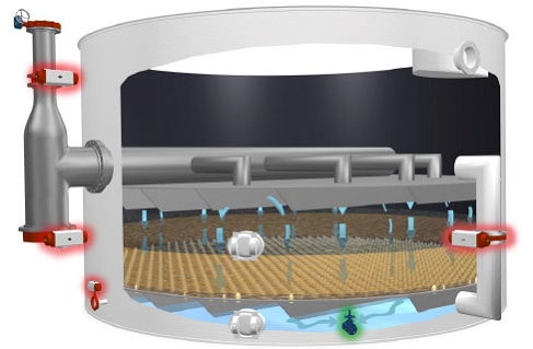 Drain down (optional) : The drain down step, described below, only occurs prior to an air scour cycle.
- Service inlet valve closed (to prevent service water entering the filter)
- Backwash outlet valve open (to allow air into the tank as water exits the tank)
- Drain valve open (to lower water level in the media compartment and plenum)
- Air scour air supply valve closed (to prevent the introduction of air until the water reaches the proper level)
- Transfer block valve closed (to prevent water from backwash storage from entering the plenum and media compartment)
The drain valve remains open until the water level drops to the top of the media bed. To reach the proper water level, the drain valve is opened for a fixed time interval, there is no way to monitor the level.
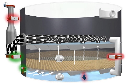
Air Scour (optional) : The valve configuration is described in the following list.
- Service inlet valve closed (to prevent new incoming water into the vessel)
- Backwash outlet valve open (to allow air to escape from the filter media compartment)
- Drain valve closed (to prevent water from going to drain)
- Air scour inlet valve open (to deliver a supply of air into the plenum and up through the strainers for the air scour cleaning of the media bed)
- Transfer valve closed (to prevent the water in the backwash storage compartment from entering the plenum)
After a set amount of time, the air scour cycle is complete, and the air scour inlet valve is closed.
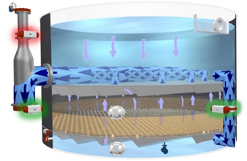 Backwash : The valve configuration is described in the following
- Service inlet valve closed (to prevent incoming water from entering the filter at the inlet distributor)
- Backwash outlet valve open (to allow dirty backwash water to exit the filter)
- Drain valve closed (to prevent backwash water going to drain before it enters the media compartment)
- Optional air scour air supply valve closed (to prevent the introduction of air into the service water)
- Optional transfer valve open (to allow water from the backwash storage compartment to flow back through the plenum and media compartment)
When the backwash storage compartment is empty, the backwash cycle is complete, and the filter is ready to resume normal service.
Valves :
Gravity filters normally have butterfly valves, although diaphragm valves can be used on smaller units. All valves except the inlet isolation valve are typically provided with automatic actuators for control via the system PLC. The drain valve has an automatic actuator only if air scour is used. The air scour inlet (if selected) and the backwash outlet valves should also be provided with adjustable travel stops so that the flow rates can be set.
Materials of Construction :
Gravity filters are typically made of carbon steel and are often assembled on site. If the water is aggressive and dissolved iron is a concern, the carbon steel can be lined with an epoxy or coal tar spray on lining. The coal tar lining provides a thicker coating but is not as robust as the epoxy.
Application :
Gravity filters are used to remove suspended solids from the service water and are typically downstream of pre-treatment clarifiers. Gravity filters are commonly used when the turbidity and color of the influent are too high for pressure filters (turbidity greater than 50 NTU and color greater than 10 APHA). Any floc carryover from the clarifier is also removed.With a lack of driving pressure, gravity filters have the advantage of being unable to drive suspended matter through the filter bed and into the effluent. The disadvantages are the large space required to house the unit, and that service water must be pumped to its use point, as all pressure is lost across the gravity filter.