Oils can exist in following or combination of three states depending upon the forces exerted on them.
Free Oil: Oil in natural state will typically be a free product, meaning it retains its typical oily & hydrophobic characteristics & which will eventually form into a layer separate from the water phase. The free phase oil can be dispersed or spread out throughout the water body due to being broken down into droplets.
Emulsions: Oils change to an emulsified state oil droplet size is drastically reduced. This happens by mechanical shear force which makes oil droplet a companion to water molecule.
Dissolved: The oils get dissolved into solution with the water due to innate characteristics, nature & external influences like sheer force.
Normally following equipments are used for Oil Removal
1. Oil Skimmers
2. API Separators
3. Parallel Plate Separators
4. DAF (Dissolved Air Floatation) Unit
Equipment like Nut Shell Filters, Coalescers, Membranes etc. are used in tertiary treatment.
1. Oil Skimmers:
Many oils can be recovered from open water surfaces by skimming devices. Considered a dependable and cheap way to remove oil, grease and other hydrocarbons from water, oil skimmers can sometimes achieve the desired level of water purity. At other times, skimming is also a cost-efficient method to remove most of the oil before using membrane filters and chemical processes. Skimmers will prevent filters from blinding prematurely and keep chemical costs down because there is less oil to process.
Because grease skimming involves higher viscosity hydrocarbons, skimmers must be equipped with heaters powerful enough to keep grease fluid for discharge. If floating grease forms into solid clumps or mats, a spray bar, aerator or mechanical apparatus can be used to facilitate removal.
However, hydraulic oils and the majority of oils that have degraded to any extent will also have a soluble or emulsified component that will require further treatment to eliminate. Dissolving or emulsifying oil using surfactants or solvents usually exacerbates the problem rather than solving it, producing wastewater that is more difficult to treat.
2. API Separators
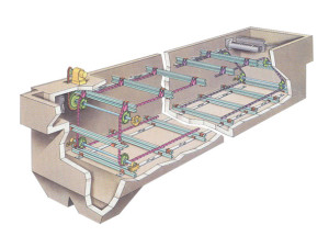
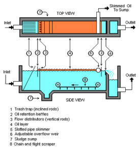
The wastewaters from large-scale industries such as oil refineries, petrochemical plants, chemical plants, and natural gas processing plants commonly contain gross amounts of oil and suspended solids. Those industries use a device known as an API oil-water separator which is designed to separate the oil and suspended solids from their wastewater effluents. The name is derived from the fact that such separators are designed according to standards published by the American Petroleum Institute (API).
The API separator is a gravity separation device designed by using Stokes Law to define the rise velocity of oil droplets based on their density and size. The design is based on the specific gravity difference between the oil and the wastewater because that difference is much smaller than the specific gravity difference between the suspended solids and water. The suspended solids settles to the bottom of the separator as a sediment layer, the oil rises to top of the separator and the cleansed wastewater is the middle layer between the oil layer and the solids.
Typically, the oil layer is skimmed off and subsequently re-processed or disposed of, and the bottom sediment layer is removed by a chain and flight scraper (or similar device) and a sludge pump. The water layer is sent to further treatment consisting usually of Electroflotation module for additional removal of any residual oil and then to some type of biological treatment unit for removal of undesirable dissolved chemical compounds.
3. Parallel plate Separator:
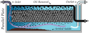
Parallel plate separators are similar to API separators but they include tilted parallel plate assemblies (also known as parallel packs). The parallel plates provide more surface for suspended oil droplets to coalesce into larger globules. Such separators still depend upon the specific gravity between the suspended oil and the water. However, the parallel plates enhance the degree of oil-water separation. The result is that a parallel plate separator requires significantly less space than a conventional API separator to achieve the same degree of separation.
4. DAF (Dissolved Air Floatation):
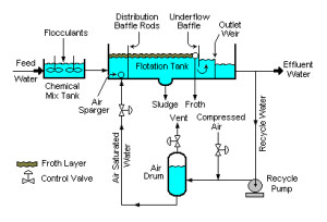
The feed water to the DAF float tank is often (but not always) dosed with a coagulant (such as ferric chloride or Aluminium Sulphate) to flocculate the suspended matter.
A portion of the clarified effluent water leaving the DAF tank is pumped into a small pressure vessel (called the air drum) into which compressed air is also introduced. This results in saturating the pressurized effluent water with air. The air-saturated water stream is recycled to the front of the float tank and flows through a pressure reduction valve just as it enters the front of the float tank, which results in the air being released in the form of tiny bubbles. The bubbles adhere to the suspended matter, causing the suspended matter to float to the surface and form a froth layer which is then removed by a skimmer. The froth-free water exits the float tank as the clarified effluent from the DAF unit.
Some DAF unit designs utilize parallel plate packing material, lamellas, to provide more separation surface and therefore to enhance the separation efficiency of the unit.
DAF systems can be categorized as circular (more efficient) and rectangular (more residence time). The former type requires just 3 minutes. The rectangular type requires 20 to 30 minutes. One of the bigger advantages of the circular type is its spiral scoop.
5. Nut Shell Filter:
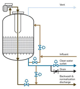
As the name suggests the Nut Shell filter contains Wallnut Shell or Pecan Shell Carbon which has highest Oil retention capacity. The Filter is like any other filter except its media needs to be scrubbed properly before taking into service again during backwash cycle. A scrubber Pump & scrubber is provided for the same.
The Filtration & Backwash cycle is briefly explained below.
A. Filtration
During the filtration cycle of the NSF the inlet feed fluid passes through inlet valve and enters the top of the vessel. The fluid is forced through the media where the solids and oil are removed. The clean filtered fluid exits through outlet valve. The vent valve remains open during filtration to either periodically or continuously based on design to remove any gas and oil from the top of the vessel.
The filtration step terminates in one of three ways:
1. Time lapses (24 hours maximum)
2. Differential pressure (14 psig) or
3. Manually
Any of these methods will start the media cleanup cycle.
During the backwash cycle, the backwash inlet and backwash outlet valve is opened. The backwash outlet valve is closed after 15 second. After closing the backwash outlet valve, Scrubber pump is started. The media inside the vessel gets fluidized during this phase and starts passing through the scrubbing pump as well as scrubbing section. When media is fully fluidized after 1 minute, the backwash outlet valve is again opened to let out the dirty water for 10 minutes. Once discharge step is completed, the next step of settling starts. In settling step all the valves and drives are closed and the fluidized media is allowed to settle down. After settling Step, Purge step is carried out. In purge step the Water passes through media in downward direction and is taken out from Purge outlet line so that residual dirt in the vessel is taken out and Media is fresh for further filtration.
